Recently I finished a cool electronics project: internet connected lights under my bed. In five steps I will guide you from project to project, each time adding functionality to what we made. In the first part I will show you how to add a cool feature to your bed by connecting six electronics parts.
Whenever I wake up at night I have to walk to the end of the room to turn on the lights. Although it is only slightly inconvenient, this is something that can we can solve by having lights that are motion activated. In this recently posted blog on hackaday.io you can see other people face the same problem, and solve it in the same smart way: https://hackaday.io/project/13207-smart-bed-lighting.
Although the Hackaday project is cool, it is possible to extend the project to be more useful for us in our daily lives. In this first post I will set you up with a minimalistic design that performs the task. Next posts I will help you connect your lights to the internet and help you do cool stuff with them.
To create this project you only need a small amount of parts. I list what I bought, and where I bought it. If you want to build soon, you can spend more money and buy the components in your local shop.
The LED strip consists of three wires:
- 12V input
- Ground blue
- Ground red
- Ground green
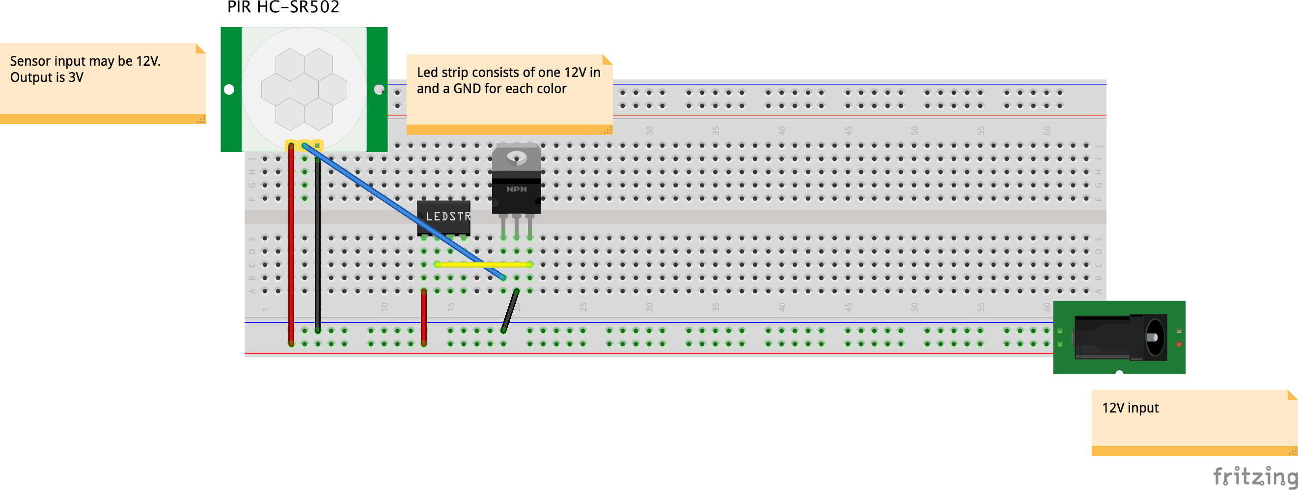
To turn on a part of the lights connect the + of the power supply to the 12V input and the – of the power supply to the ground of one of the colours. Connecting and disconnecting the connection to the ground can also be done with an electronic switch: the transistor that we bought. To create a connection we need a small amount of power on the center pin of the transistor.
This small amount of power can be given by the motion detector. On this website we find that the sensor can operate from 5 to 20 volts (our 12 volts is perfect), and that the output of the sensor is 3.3 volts: http://henrysbench.capnfatz.com/henrys-bench/arduino-sensors-and-input/arduino-hc-sr501-motion-sensor-tutorial/ . This 3.3 volts can be put on the center pin of the transistor to trigger the lights.
Our motion triggered lights can be achieved by building this diagram:
Facebook Comments (
G+ Comments ()